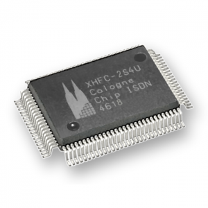
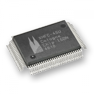
HFC-E1
Recommended for new projects
- In mass production
- Available from stock in volumes
Benefits
- Integrated PCI bus interface
- Low power consumption
- Easy inter-chip connection to telecom ICs
- Fully digital chip architecture
- Excellent lead times
- Competitive price
- Comprehensive software support
Summary
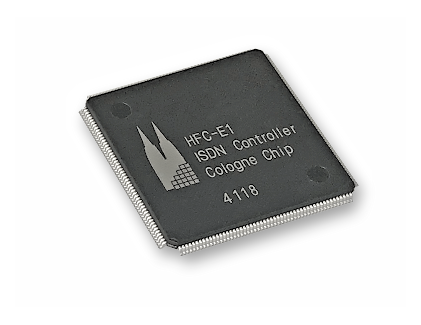
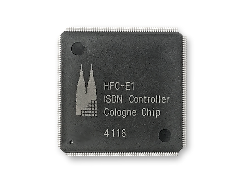
The HFC-E1 is a HDLC B- and D-channel controller with integrated E1 (S2M) interface and can be used for ISDN primary rate lines with 30 B- and two D-channels for a bandwidth of 2.048 Mbit/s. All channels are served fully duplex by deep FIFOs.
The integrated universal bus interface of HFC-E1 can be configured to PCI, ISA Plug and Play, PCMCIA, parallel microprocessor interface or SPI. A PCM128 / PCM64 / PCM30 interface for CODEC or inter chip connection is also integrated.
Parametrics
| Technology Element | Details |
| Interface | E1 (S2M) |
| Bus interfaces | PCI, PCMCIA, SPI, 8 bit parallel |
| CODEC or inter-chip connection | PCM128 / PCM64 / PCM30, H.100 |
| Technology features | CMOS 3.3 V technology, 5 V tolerant on nearly all inputs |
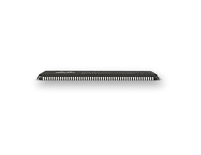
| Package | LQFP 208 |
Evaluation Board
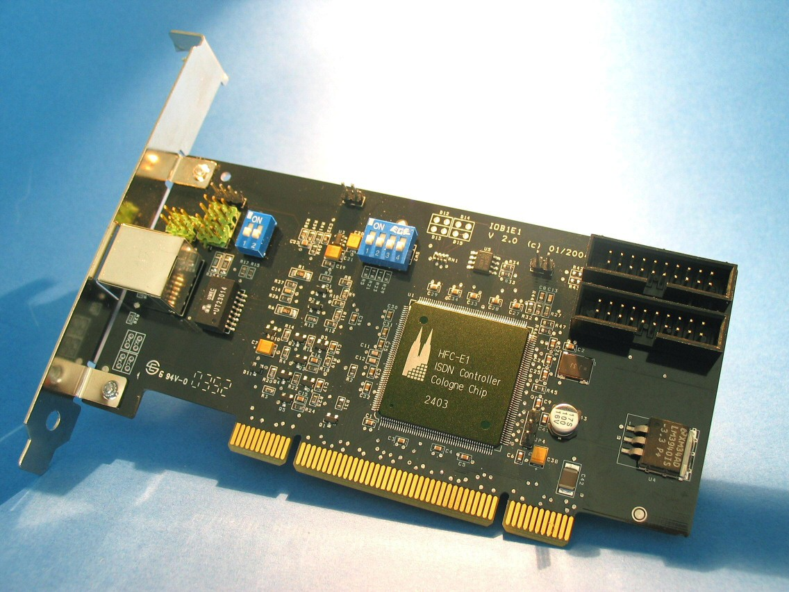
The HFC-E1 Evaluation Board PCI card allows to use the integrated E1 (S2M) interface and is made of the following functional parts:
- the HFC-E1 microchip
- one RJ45 connectors
- a PCI bus connector
- a PCM interface connector
- 100Ω termination switches for each interface
- TE/NT mode jumper switches
Software
Driver software plays an important role in all ISDN projects. This consideration leads to one of the basic principles of Cologne Chip: individual support for each project.
By having broad knowledge about ISDN applications, the support team of Cologne Chip will assist in finding the best approach regarding system architecture and concerning software aspects.
Linux drivers are available for all chips as open source software. Under the terms of GPL (GNU Public Licence) the source code of the Linux drivers may be used free of royalities.
Wheter a project is done as an in-house development or in cooperation with a design house as 3rd-party, Cologne Chip is committed to in-depth technical support for fast time-to-market.
Go to the official repository.
Transformer Selection Guide
Customers of Cologne Chip can choose from a variety of transformers. The relevant requirements for selecting the right transformer for each ISDN Interface are as follows:
compatible to HFC-E1
- Turns ratio of 2.4:1 (line side : chip side) for transmit and 1:1 for receive path
- Center tap on chip side (required for Cologne Chip receiver circuitry)
Several companies provide transformers and transformer modules that can be used with our ISDN Basic Rate and Primary Rate Interface controllers. Most popular are SMD modules with chokes for EMI reasons.
Here you can find all relevant documentation of HFC-E1. Files are gouped by topic, so you will have quick access to the requested information. Please feel free to contact us for any questions.
Note: Data can change without notice. Parts of the information presented may be protected by patent or other rights.
Packaging Regulations of HFC-E1
HFC-E1 comes on trays in vacuum sealed packages according to industry standards. Please have a look at the packaging regulations:
- LQFP 208 package
- Pin pitch: 0.5 mm
- JEDEC tray
- MSL 3
- Ordering Code: HFC-E1
- Country of Origin: Taiwan (TW)
- RoHS/REACH compliant
Profiles for soldering reflow of HFC-E1
The recommended profiles for soldering reflow of HFC-E1 for Pb-free assembly as well as Sn-Pb eutectic mainly correspond to the commonly applied JEDEC Standard JSTD-020C. To ensure best surface mounting quality, it is recommended to use the provisions of Pb-free assembly. The soldering profile graph (1.) and table (2.) underneath illustrate the respective soldering reflow.
Surface mount products may have a crack when thermal stress is applied during surface mount assembly if they have absorbed atmospheric moisture. It is recommended that these products are handled under specific conditions.
These conditions are described in the following handling recommendations in table (3.).
Profile for Soldering Reflow
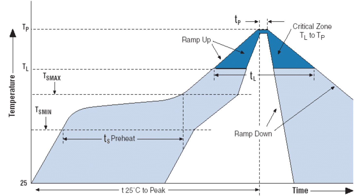
Details Soldering Reflow Profile
| Profile Feature |
Pb-free assembly | Sn-Pb eutectic assembly |
| Average ramp-up rate (TL to TP) | 3°C/second max. | 3°C/second max. |
| Preheat - Temperature Min (TSMIN) - Temperature Max (TSMAX) - Time (min to max) (tS) |
150°Cc 200°Cc 60-180 secondsc |
100°Cc 150°Cc 60-120 secondsc |
| TSMAX to TL – Ramp-up Rate |
3°C/second max | |
| Time maintained above: - Temperature (TL) - Time (tL) |
217°Cc 60-150 secondsc |
183°Cc 60-150 seconds |
| Peak Temperature (TP) | 245 +0/-5°C | 225 +0/-5°C |
| Time within 5°C of actual Peak Temperature (tP) | 20-40 seconds | 10-30 seconds |
| Ramp-down Rate | 6°C/second max. | 6°C/second max. |
| Time 25°C to Peak Temperature | 8 minutes max. | 6 minutes max. |
Handling recommendations
| Package Type |
Storage Condition
after unpacking
as maximum
|
Rebake Condition
as minimum
|
| MPQFP 208 (Pb-free) |
Within 168 hours
(30 °C/60% RH)
MSL 3
|
125 °C
24 hours
|
